All Projects
Browse by category, or expand the full list below.
ProAmpac — R&D Engineering Internship
Internship
Aerodynamic CFD Validation: From Unstructured O-Meshes to Multi-Block Structured C-Meshes
Personal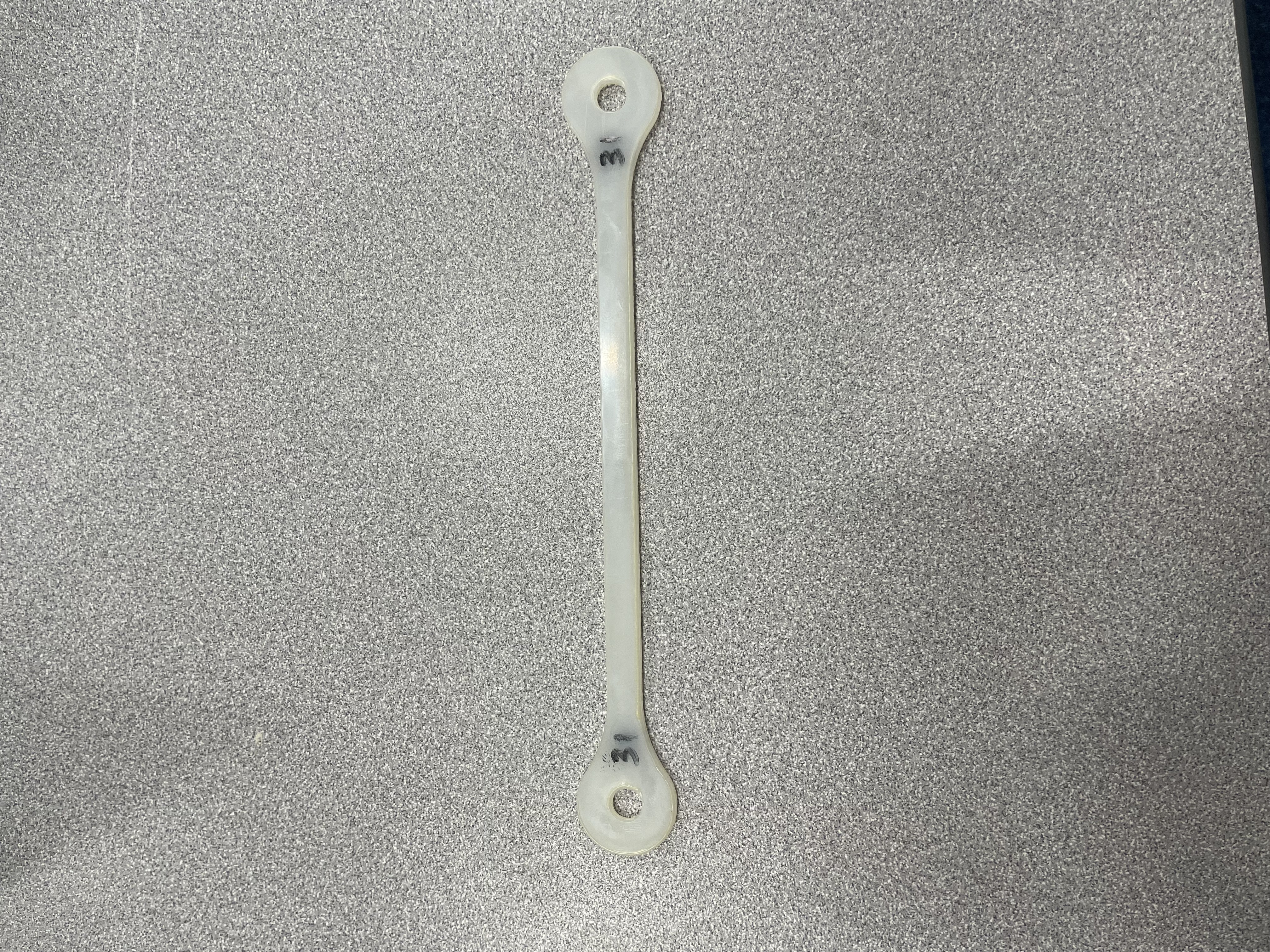
Optimized Aircraft Landing Gear Link Design
School Project
Custom ESP32-C3 Micro Quadcopter: Flight Dynamics & Discrete Power Architecture
Personal
Reverse-Engineered Vacuum Plate
Internship
Hovercraft Engine Mount Design
School Project
Packing Station Arm Joint Prototypes
Internship
Modular Packing Station Design
Internship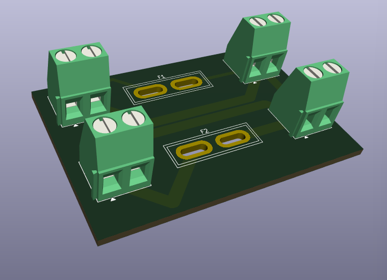
CNC Mill Power Distribution Board: Dual-Rail PCB Design in KiCad
Personal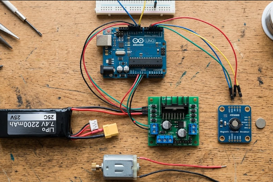
Custom Closed-Loop DC Servomechanism & Mechatronic Test Bench (Work in Progress)
Personal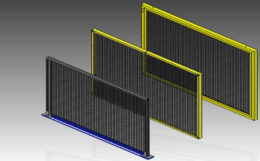
Machine Safety Guard Design
Internship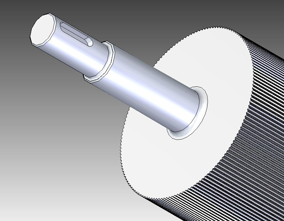
Micro-Flute Nip Roller Redesign
Internship
Custom Encoder Test Fixture
Internship
Hand-Machined Hammer & Bar
School Project
Mechanical Differential Assembly
Personal
Precision Punch Mechanism Rebuild
Internship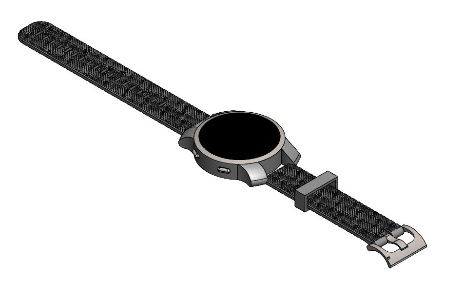
Garmin Smartwatch Housing & Strap
Personal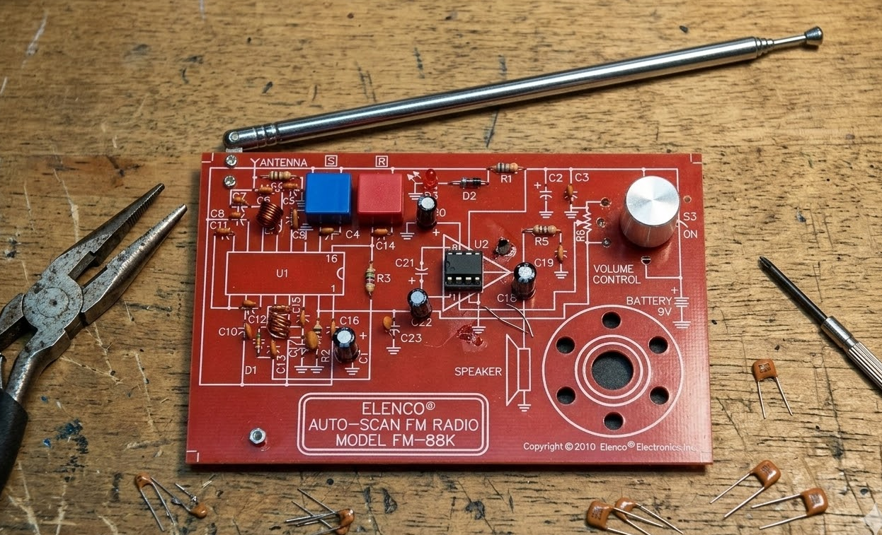
FM-88K Auto-Scan Receiver Assembly & Analysis
School Project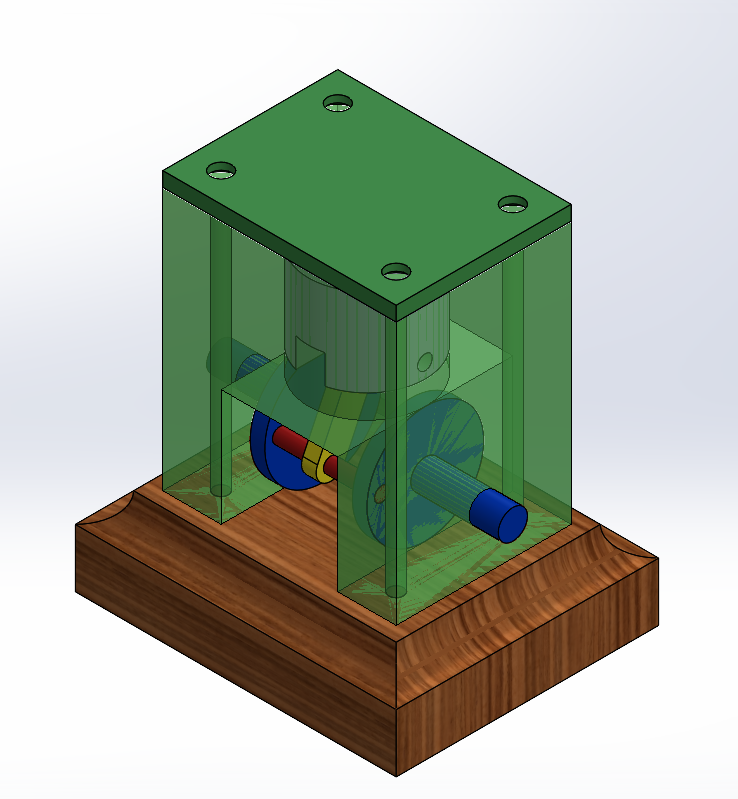
Single-Cylinder Piston Engine Assembly
School Project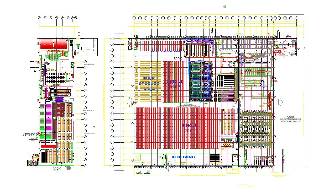
Production Floor Layout Drafting
Internship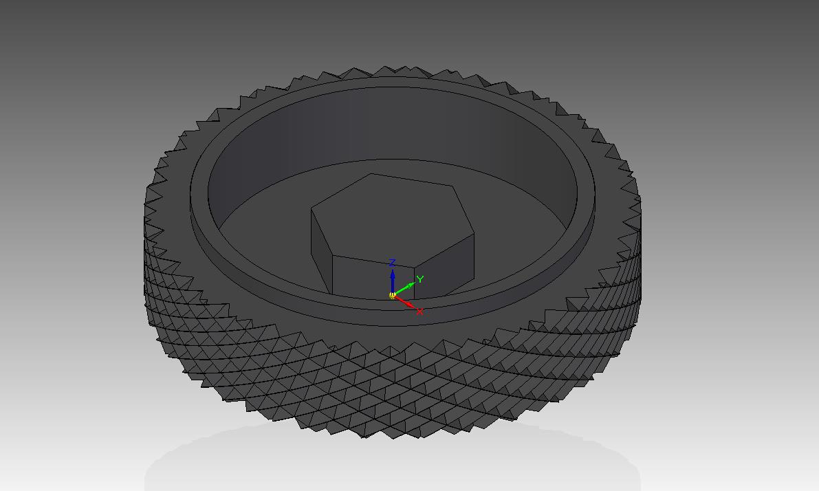
Custom Ratchet Wrench End Cap
Internship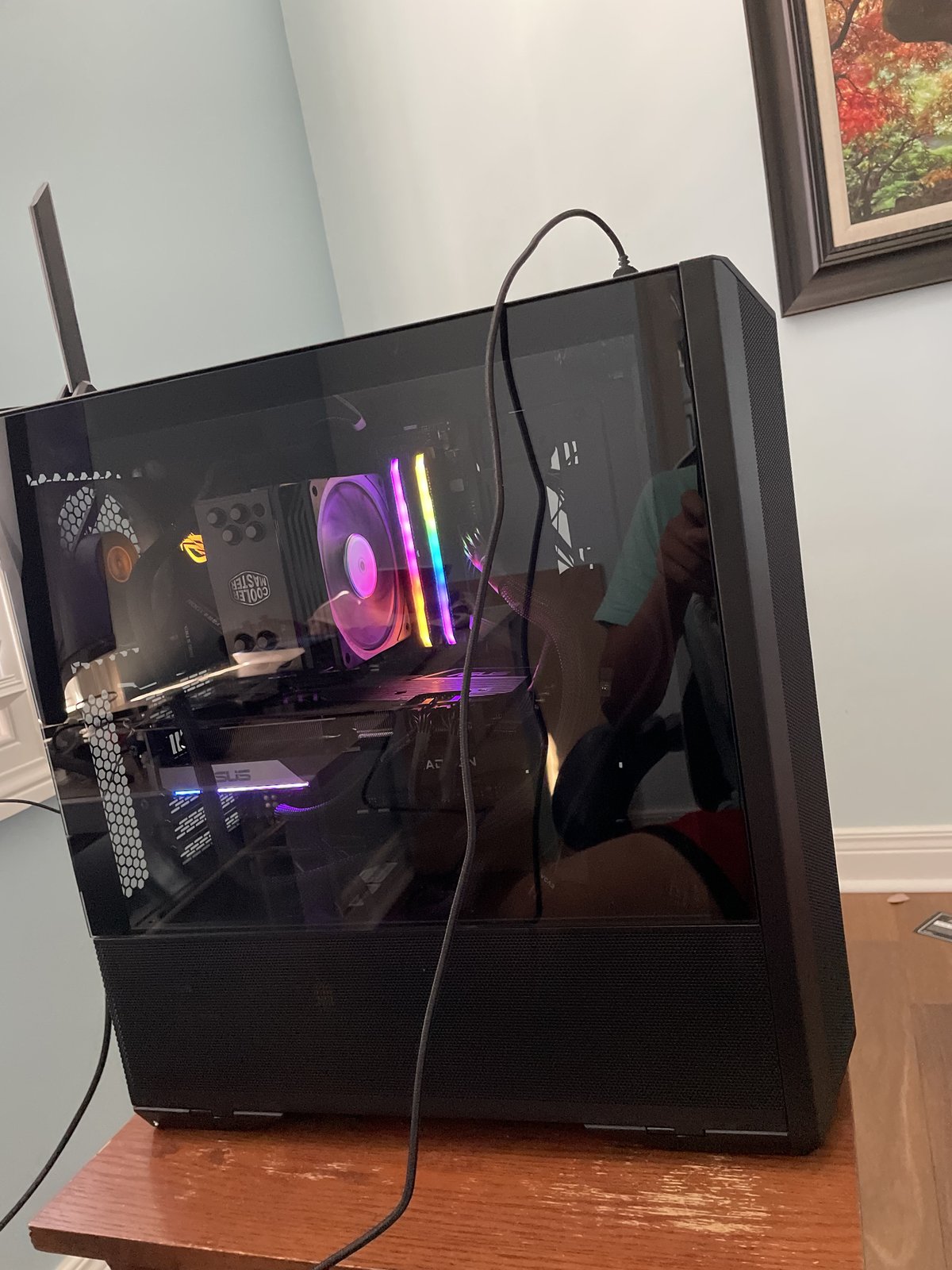
Custom Gaming PC Build
Personal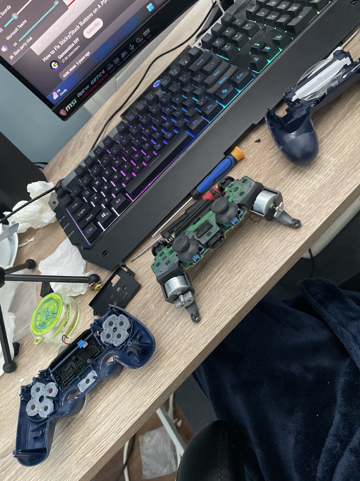
PS4 Controller Refurbishment & USB-C Mod
Personal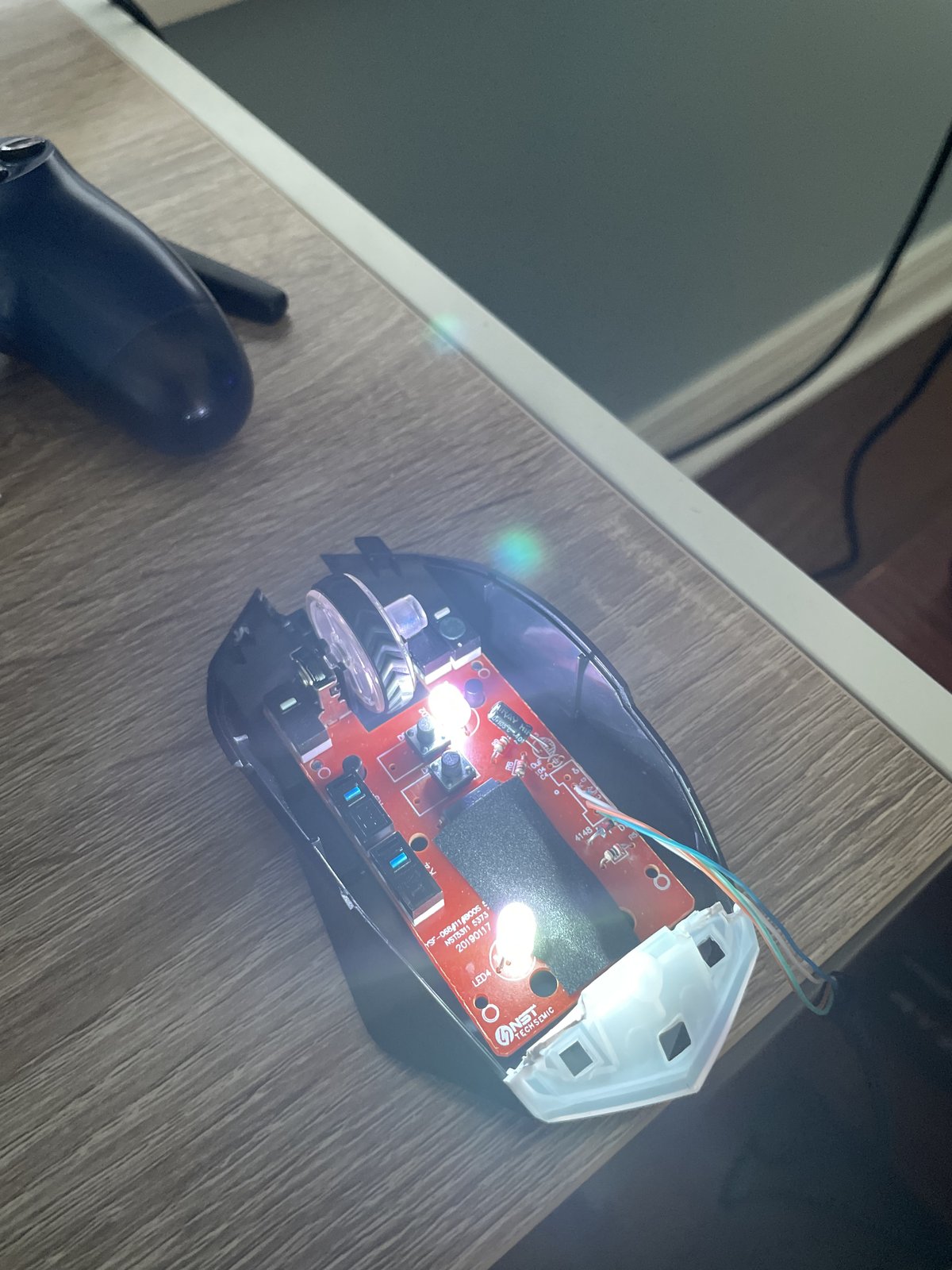
Custom Gaming Mouse Build
Personal
Nerf Blaster Modifications
Personal
Desktop 3-Axis CNC Router & Milling Machine (Work in Progress)
Personal
4-Axis SCARA Robotic Manipulator (Work in Progress)
Personal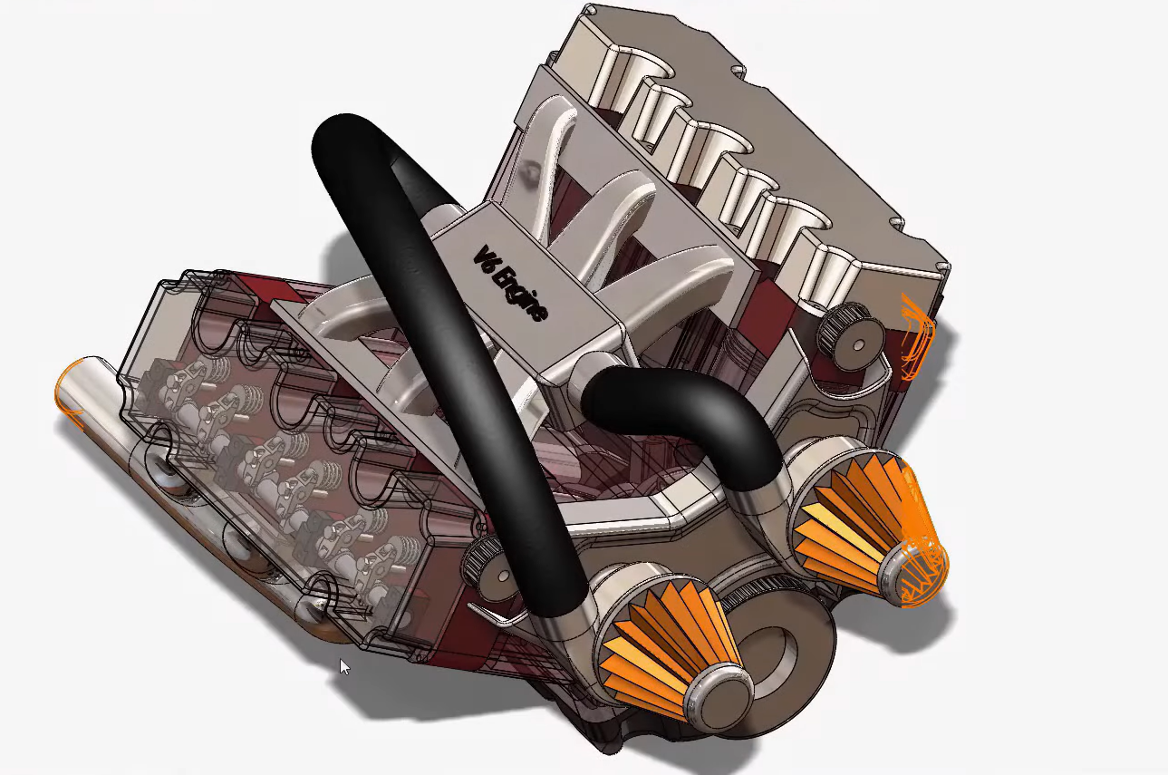
V6 Engine CAD Development (Work in Progress)
PersonalDesign & CAD
Key Specifications
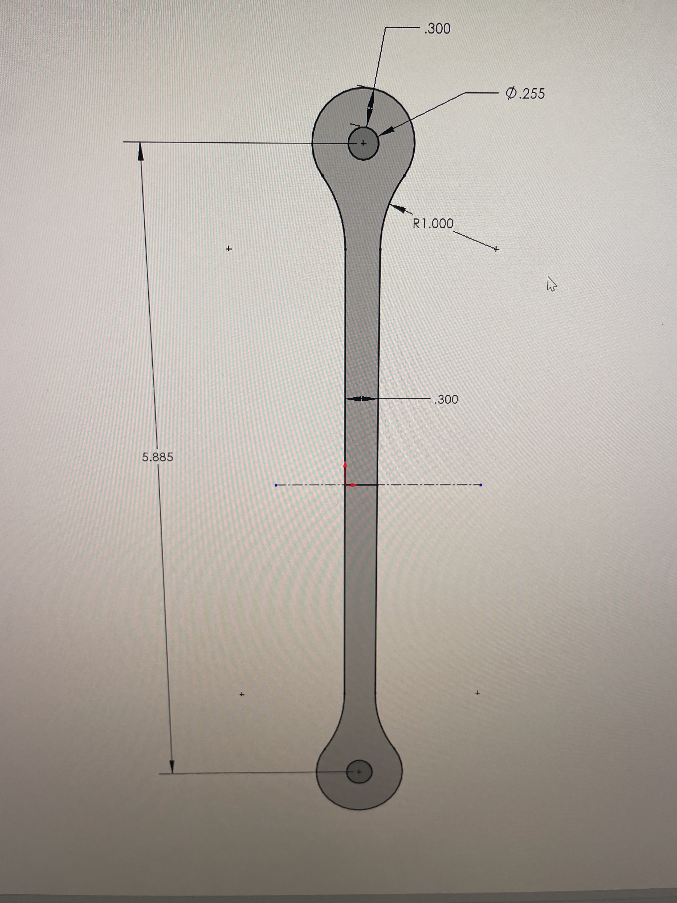
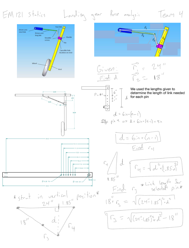
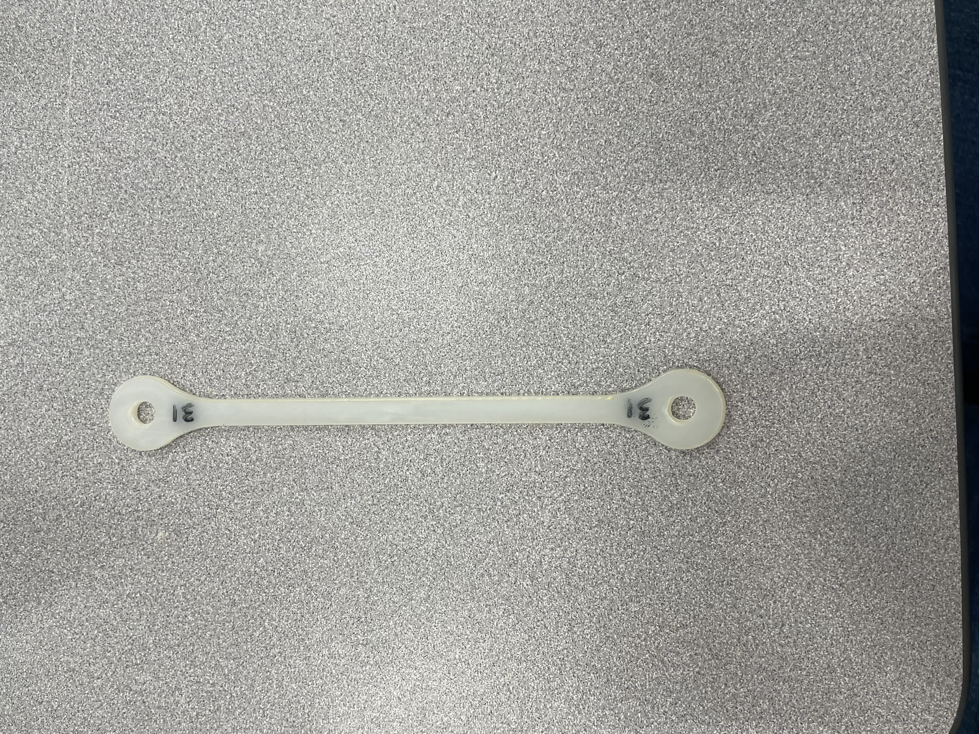
Center-to-center distance: 5.908 in | Cross-section width: 0.300 in | Material thickness: 0.094 in Nylon 6/6
Design Decisions
Implemented a dogbone geometry to reduce weight while maintaining strength. 1.000 in radius fillets minimize stress concentrations between the pin joints and central body. Hole diameters include 0.006 in clearance to account for laser cutter kerf and ensure proper fit with shoulder screws.
Engineering Analysis
Applied load: 155 lbs | Net cross-sectional area: 0.0276 in² | Resulting stress: 5,616 psi
Using Nylon 6/6 yield strength ≈ 10,000 psi → Calculated FoS: 1.78
Failure predicted as tensile rupture at the narrowest cross-section. Pin-hole bearing stress also evaluated to ensure sufficient wall thickness and prevent tear-out failure.
Load Test Validation
Results
Design load: 155 lbs | Link successfully sustained full design load
Measured elastic deformation: 0.062 in (0.93%) — well below the 10% failure threshold.
Predicted deformation: 0.107 in | Actual: 0.062 in | FoS: 1.78 Validated
Reflection
The link exhibited lower deformation than predicted by the simplified FL/EA model. This difference is likely due to the dogbone geometry, where the widened ends and fillets increase the average stiffness compared to the uniform cross-section assumed in the analytical model. Selecting Pin 4 also reduced the required link length by over 12% compared to standard Pin 6 designs, resulting in a lighter and more competitive component.
System Overview
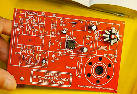
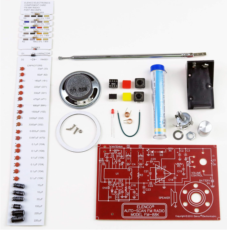
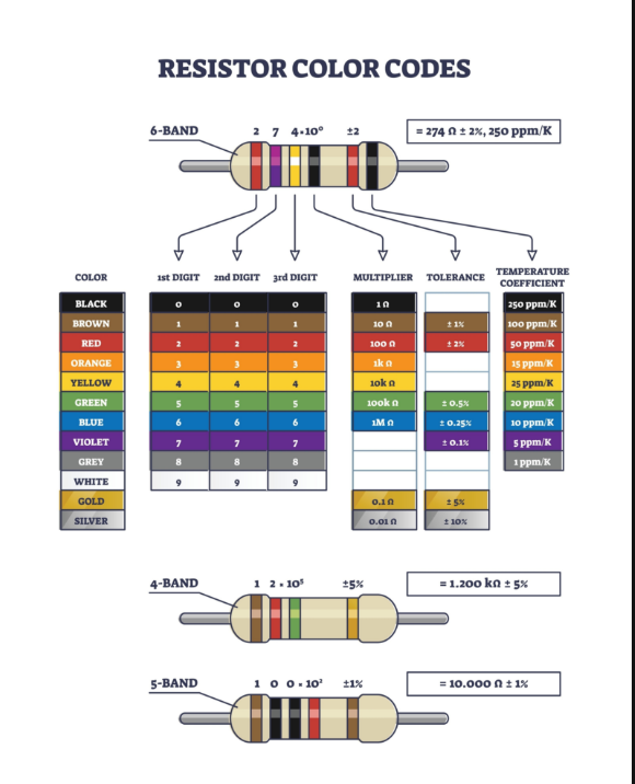
The receiver is composed of three primary subsystems: an RF Tuning Circuit using an LC resonant network and varactor diode to select the desired frequency, a Receiver IC (TDA7088T) that demodulates the FM signal and extracts audio, and an Audio Amplifier (LM386) that drives an 8Ω speaker.
RF Tuning Principle
The radio selects stations using a resonant LC circuit. By varying capacitance using a varactor diode, the circuit shifts its resonant frequency, enabling the receiver to automatically scan across the 88–108 MHz FM spectrum.
Audio Amplification
The demodulated audio signal is amplified using an LM386 low-voltage audio power amplifier. Default gain: 20 (26 dB), capable of driving an 8Ω speaker, designed for low-power portable audio applications.
Assembly & Manufacturing
The PCB was populated with 40+ through-hole electronic components including resistors (5% tolerance), ceramic and electrolytic capacitors, RF tuning inductors, and integrated circuits. Proper component orientation and clean solder joints were essential for reliable circuit operation.
Challenges
One challenge was ensuring the inductor coils used in the RF tuning stage were properly formed and spaced, as coil geometry directly affects inductance and therefore the tuning range of the receiver. Additional troubleshooting included verifying solder joints and confirming signal flow through the amplifier stage using a multimeter.
Reflection
This project provided practical experience with radio frequency circuits, signal demodulation, and PCB population. It helped bridge theoretical concepts from electromagnetic and circuit theory with real hardware implementation, reinforcing how inductors, capacitors, and amplifiers interact within a communication system.
Current Progress
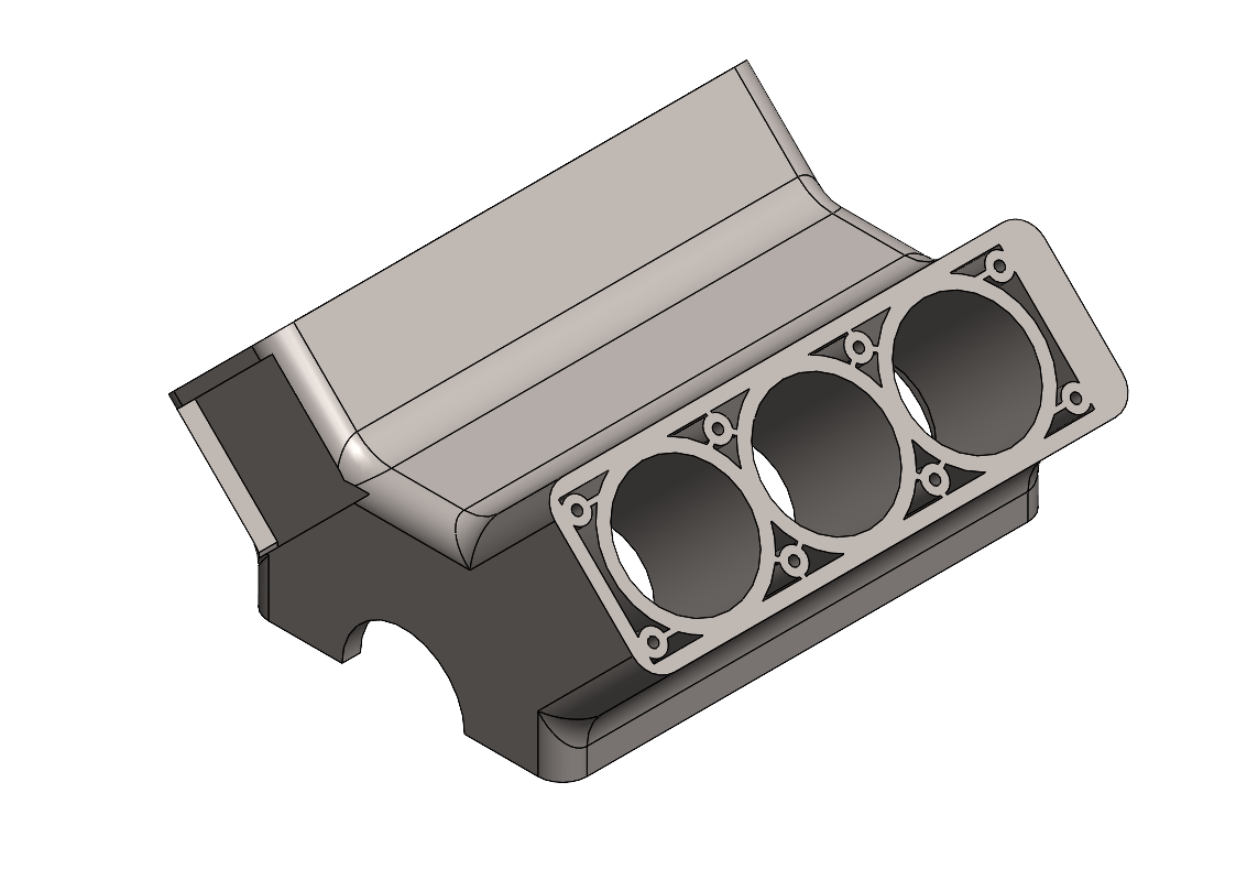
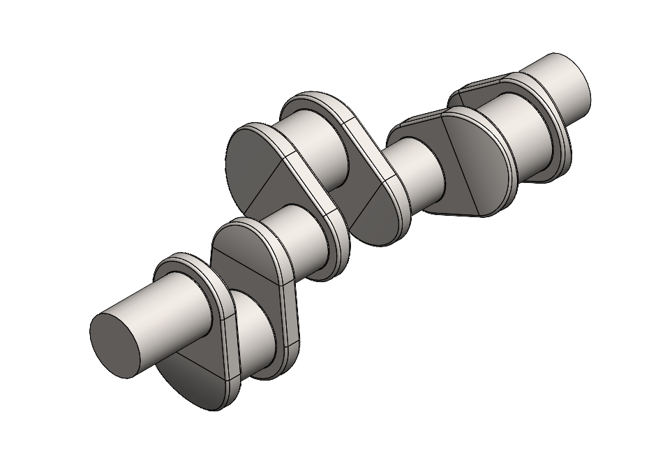
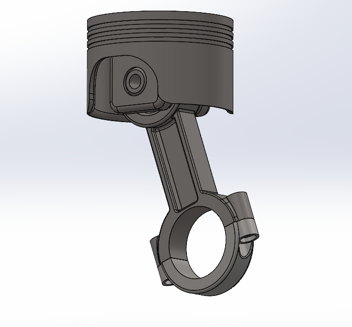
The project is being completed component-by-component, beginning with the core structural and rotating elements. Current completed components — crankshaft, piston, and engine block — establish the primary kinematic relationship between the pistons and crankshaft, converting reciprocating piston motion into rotational output.
Assembly Stages
1. Lower Block Assembly — integration of crankshaft, pistons, and block
2. Upper Block Assembly — cylinder head, valvetrain, and camshaft components
3. Final System Assembly — belt drive, accessory components, and intake/exhaust systems
Planned Components
Rocker Arm, Cylinder Head, Exhaust Manifold, Air Filter, Camshaft, Rocker Spring and Valve, Belt Wheels, Valves Cover, Front Cover, Oil Pan, Turbocharger, Intake Manifold, Bushings and Camshaft Retainer
Mechanical Principles
The engine operates using a crank-slider mechanism where piston motion is transferred to the crankshaft through connecting rods. Piston position is governed by:
x = r·cos(θ) + √(l² − (r·sin(θ))²)
where r = crank radius, l = connecting rod length, θ = crank angle. This relationship determines stroke length and volumetric displacement.
Goal
The completed project will result in a fully detailed V6 engine assembly capable of motion simulation, providing a deeper understanding of engine architecture, mechanical linkages, and multi-part CAD system integration. The final assembly will consist of 16 engineered components across 3 major assembly stages.